After the exposure of certain secret operations carried out by the National Security Agency (NSA) of U.S.A, by its former contractor, Edward Snowden, most of the governments, corporations and even individuals started to think more about security. Edward Snowden is a traitor for some while a whistle-blower for others. The Washington Post newspaper published details from a document revealed by Edward Snowden on 30th October, 2013, which was terrible news for two Silicon Valley tech giants, Google and Yahoo. This highly confidential document revealed how NSA intercepted communication links between data centers of Google and Yahoo to carry out a massive surveillance on their hundreds of millions of users. Further, according to the document, NSA sends millions of records every day from the Yahoo and Google internal networks to data warehouses at the agency’s headquarters in Fort Meade, Md. After that, field collectors process and send back new records — including metadata, which indicate who sent or received e-mails and when, as well as the content such as text, audio and video.
How is this possible? How come an intruder (in this case it’s the government) intercepts the communication channels between two data centers and gets access to the data? Even though Google used a secured communication channel from the user’s browser to the Google front-end server, from there onward, and between the data centers the communication was in cleartext. As a response to this extremely disturbing exposure, Google rushed into securing all its communication links between data centers with encryption. Transport Layer Security (TLS) plays a major role in securing data transferred over communication links. In fact Google is one of the first out of all tech giants to realize the value of TLS. Google made TLS the default setting in Gmail in January 2010 to secure all Gmail communications and four months later introduced an encrypted search service located at https://encrypted.google.com. In October 2011 Google further enhanced its encrypted search and made google.com available on HTTPS and all Google search queries and the result pages were delivered over HTTPS. HTTPS is in fact the HTTP over TLS. We discuss more on HTTP over TLS later in this blog.
In addition to establishing a protected communication channel between the client and the server, TLS also allows both the parties to identify each other. In the most popular form of TLS, which everyone knows and uses in day-to-day life on the Internet, only the server authenticates to the client — this is also known as one-way TLS. In other words, the client can identify exactly the server he or she is going to communicate with. This is done by observing and matching the server’s certificate with the server URL, which the user hits on the browser. As we proceed in this blog, we will further discuss how exactly this is done in detail. In contrast to one-way TLS, mutual authentication identifies both the parties — the client and the server. The client knows exactly the server he or she is going to communicate with and the server knows who the client is.
The Evolution of Transport Layer Security (TLS)
TLS has its roots in SSL (Secure Sockets Layer). Netscape Communications (then Mosaic Communications) introduced SSL in 1994 to build a secured channel between the Netscape browser and the web server it connects to. This was an important need at that time, just prior to the dot-com bubble. The SSL 1.0 specification was never released to the public, because it was heavily criticized for the weak cryptographic algorithms that were used. In November 1994, Netscape released the SSL 2.0 specification with many improvements. Most of its design was done by Kipp Hickman, with much less participation from the public community. Even though it had its own vulnerabilities, it earned the trust and respect of the public as a strong protocol. The very first deployment of SSL 2.0 was in Netscape Navigator 1.1. In January 1996, Ian Goldberg and David Wagner discovered a vulnerability in the random-number-generation logic in SSL 2.0. Mostly due to U.S.A export regulations, Netscape had to weaken its encryption scheme to use 40-bit long keys. This limited all possible key combinations to a million million, which were tried by a set of researchers in 30 hours with many spare CPU cycles; they were able to recover the encrypted data.
SSL 2.0 was completely under the control of Netscape and was developed with no or minimal inputs from others. This encouraged many other vendors including Microsoft to come up with their own security implementations. As a result Microsoft developed its own variant of SSL in 1995, called Private Communication Technology (PCT). PCT fixed many security vulnerabilities uncovered in SSL 2.0 and simplified the SSL handshake with fewer round trips required establishing a connection. Among the differences between SSL 2.0 and PCT, the non-encrypted operational mode introduced in PCT was quite prominent. With non-encrypted operational mode, PCT only provides authentication — no data encryption. As discussed before, due to the U.S.A export regulation laws, SSL 2.0 had to use weak cryptographic keys for encryption. Even though the regulations did not mandate to use weak cryptographic keys for authentication, SSL 2.0 used the same weak cryptographic keys used for encryption, also for authentication. PCT fixed this limitation in SSL 2.0 by introducing a separate strong key for authentication.
Netscape released SSL 3.0 in 1996 having Paul Kocher as the key architect. This was after an attempt to introduce SSL 2.1 as a fix for the SSL 2.0. But it never went pass the draft stage and Netscape decided it was the time to design everything from ground up. In fact, Netscape hired Paul Kocher to work with its own Phil Karlton and Allan Freier to build SSL 3.0 from scratch. SSL 3.0 introduced a new specification language as well as a new record type and a new data encoding technique, which made it incompatible with the SSL 2.0. It fixed issues in its predecessor, introduced due to MD5 hashing. The new version used a combination of the MD5 and SHA-1 algorithms to build a hybrid hash. SSL 3.0 was the most stable of all. Even some of the issues found in Microsoft PCT were fixed in SSL 3.0 and it further added a set of new features that were not in PCT. In 1996, Microsoft came up with a new proposal to merge SSL 3.0 and its own SSL variant PCT 2.0 to build a new standard called Secure Transport Layer Protocol (STLP).
Due to the interest shown by many vendors in solving the same problem in different ways, in 1996 the IETF initiated the Transport Layer Security working group to standardize all vendor-specific implementations. All the major vendors, including Netscape and Microsoft, met under the chairmanship of Bruce Schneier in a series of IETF meetings to decide the future of TLS. TLS 1.0 (RFC 2246) was the result; it was released by the IETF in January 1999. The differences between TLS 1.0 and SSL 3.0 aren’t dramatic, but they’re significant enough that TLS 1.0 and SSL 3.0 don’t interoperate. TLS 1.0 was quite stable and stayed unchanged for seven years, until 2006. In April 2006, RFC 4346 introduced TLS 1.1, which made few major changes to 1.0. Two years later, RFC 5246 introduced TLS 1.2, which is the latest finalized specification at the time of this writing. TLS 1.3 is around the corner, but not yet finalized. The first draft of the TLS 1.3 was published in April 2014 and since then it’s being discussed and refined under the IETF network working group.
Transmission Control Protocol (TCP)
Understanding how Transmission Control Protocol (TCP) works provides a good background to understand how TLS works. TCP is a layer of abstraction of a reliable network running over an unreliable channel. IP (Internet Protocol) provides host-to-host routing and addressing. TCP/ IP is collectively known as the Internet Protocol Suite, was initially proposed by Vint Cerf and Bob Kahn. The original proposal became the RFC 675 under the network working group of IETF in December 1974. After a series of refinements, the version 4 of this specification was published as two RFCs: RFC 791 and RFC 793. The former talks about the Internet Protocol (IP), while the latter is about the Transmission Control Protocol (TCP).
The TCP/IP protocol suite presents a 4-layered model for network communication as shown in Figure 1. Each layer has its own responsibilities and communicates with each other using a well-defined interface. For example, the Hypertext Transfer Protocol (HTTP) is an application layer protocol, which is transport layer protocol agnostic. HTTP does not care how the packets are transported from one host to another. It can be over TCP or UDP (User Datagram Protocol), which are defined at the transport layer. But in practice, most of the HTTP traffic goes over TCP. This is mostly due to the inherent characteristics of TCP. During the data transmission, TCP takes care of retransmission of lost data, ordered delivery of packets, congestion control and avoidance, data integrity and many more. Neither the TCP nor the UDP takes care of how the internet layer operates. The Internet Protocol (IP) functions at the internet layer. Its responsibility is to provide a hardware-independent addressing scheme to the messages pass-through. Finally it becomes the responsibility of the network access layer to transport the messages via the physical network. The network access layer interacts directly with the physical network and provides an addressing scheme to identify each device the messages pass-through. The Ethernet protocol operates at the network access layer.
Our discussion from here onward focuses only on TCP, which operates at the transport layer. Any TCP connection bootstraps with a 3-way handshake. In other words TCP is a connection-oriented protocol and the client has to establish a connection with the server prior to the data transmission. Before the data transmission begins between the client and the server, each party has to exchange with each other, a set of parameters. These parameters include, the starting packet sequence numbers and many other connection specific parameters. The client initiates the TCP 3-way handshake, by sending a TCP packet to the server. This packet is known as the SYN packet. SYN is a flag set in the TCP packet. The SYN packet includes a randomly picked sequence number by the client, the source (client) port number, destination (server) port number and many other fields as shown in the Figure 2. If you look closely at the Figure 2 you will notice that the source (client) IP address and the destination (server) IP address are outside the TCP packet and are included as part of the IP packet. As discussed before, IP operates at the network layer and the IP addresses are defined to be hardware-independent. Another important field here that requires our attention is the TCP Segment Len field. This field indicates the length of the application data this packet carries. For all the messages sent during the TCP 3-way handshake the value of the TCP Segment Len field will be zero.
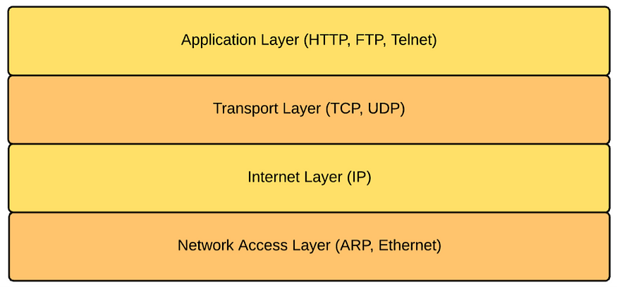
Figure 1. TCP/IP stack: protocol layer
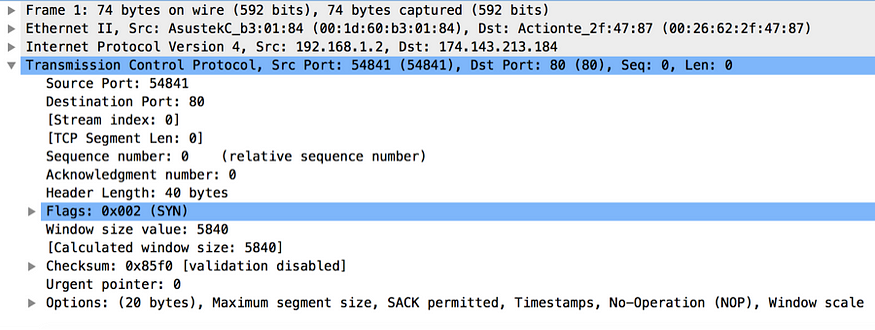
Figure 2. TCP SYN packet captured by Wireshark
Once the server receives the initial message from the client, it too picks its own random sequence number and passes it back in the response to the client. This packet is known as the SYN ACK packet. The two main characteristics of TCP: error control (recover from lost packets) and ordered delivery require each TCP packet to be identified uniquely. The exchange of sequence numbers between the client and the server helps to keep that promise. Once the packets are numbered, both the sides of the communication channel know, which packets get lost during the transmission, duplicate packets and how to order a set of packets, which are delivered in a random order. Figure 3 shows a sample TCP SYN ACK packet captured by Wireshark. This includes the source (server) port, destination (client) port, server sequence number and the acknowledgement number. Adding one to the client sequence number found in the SYN packet derives the acknowledgement number. Since we are still in the 3-way handshake, the value of the TCP Segment Len field is zero.
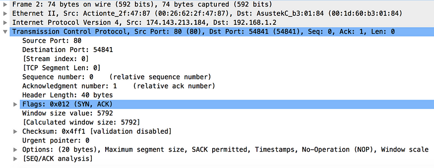
Figure 3. TCP SYN ACK packet captured by Wireshark
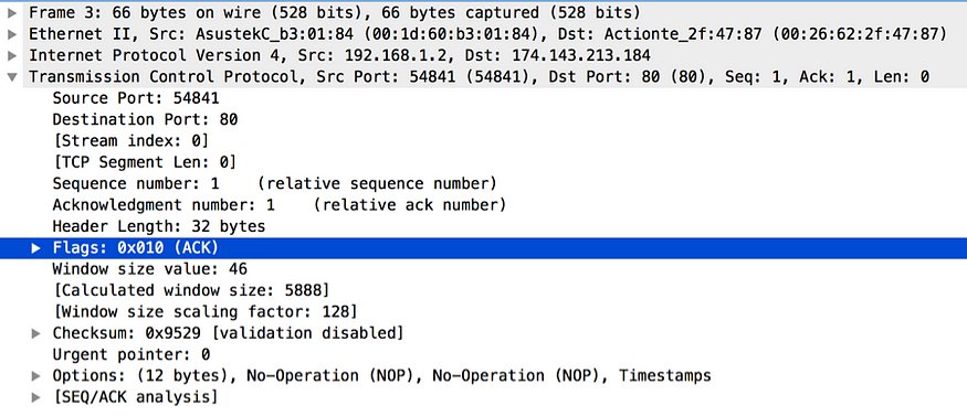
Figure 4. TCP ACK packet captured by Wireshark
To complete the handshake the client will once again send a TCP packet to the server to acknowledge the SYN ACK packet it received from the server. This is known as the ACK packet. Figure 4 shows a sample TCP ACK packet captured by Wireshark. This includes the source (client) port, destination (server) port, initial client sequence number + 1 as the new sequence number and the acknowledgement number. Adding one to the server sequence number found in the SYN ACK packet derives the acknowledgement number. Since we are still in the 3-way handshake, the value of the TCP Segment Len field is zero.
Once the handshake is complete, the application data transmission between the client and the server can begin. The client sends the application data packets to the server immediately after it sends the ACK packet. The transport layer gets the application data from the application layer. The Figure 5 is a captured message from Wireshark, which shows the TCP packet corresponding to an HTTP GET request to download an image. The HTTP, which operates at the application layer, takes care of building the HTTP message with all relevant headers and passes it to the TCP at the transport layer. Whatever the data it receives from the application layer, the TCP encapsulates with its own headers and passes it through the rest of the layers in the TCP/IP stack. How TCP derives the sequence number for the first TCP packet, which carries the application data, is explained under the section ‘How does TCP sequence numbering work?’. If you look closely at the value of the TCP Segment Len field in Figure 5, you will notice that it is now set to a non-zero value.
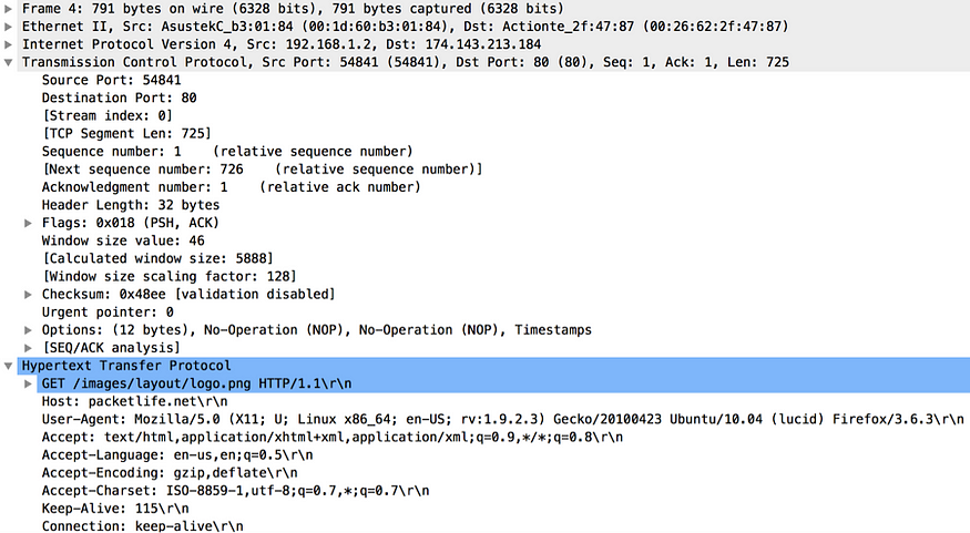
Figure 5. TCP packet corresponding to an HTTP GET request to download an image captured by Wireshark
Once the application data transmission between the client and the server begins, the other should acknowledge each data packet sent by either party. As a response to the first TCP packet sent by the client, which caries application data, the server will respond with a TCP ACK packet, as shown in Figure 6.

Figure 6. TCP ACK from the server to the client captured by Wireshark
How does TCP sequence numbering work?
Whenever either of the two parties at either end of the communication channel wants to send a message to the other, it sends a packet with the ACK flag as an acknowledgement to the last received sequence number from that party. If you look at the very first SYN packet (Figure 2) sent from the client to the server, it does not have an ACK flag, because prior to the SYN packet, the client didn’t receive anything from the server (nothing to acknowledge). From there onward, every packet sent either by the server or the client, has the ACK flag and the Acknowledgement Number field in the TCP packet.
In the SYN ACK packet (Figure 3) from the server to the client, the value of the Acknowledgement Number is derived by adding one to the sequence number of the last packet received by the server (from the client). In other words, the Acknowledgement Number field here, from the server to the client represents the sequence number of the next expected packet. Also if you closely look at the at the TCP Segment Len field in each TCP packet of the 3-way handshake, the value of it is set to zero. Even though we mentioned before that the Acknowledgement Number field in SYN ACK is derived by adding one to the sequence number found in the SYN packet from the client, precisely what happens is the server adds 1 + the value of the TCP Segment Len field from the client to the current sequence number to derive the value of the Acknowledgement Number field. The same applies to the ACK packet (Figure 4) sent from the client to the server. Adding 1 + the value of the TCP Segment Len field from the server, to the sequence number of the last packet received by the client (from the server) derives the Acknowledgement Number field there. The value of the sequence number in the ACK packet is the same as the value of the Acknowledgement Number in the SYN ACK packet from the server.
The client starts sending real application data only after the 3-way handshake is completed. The Figure 5 shows the first TCP packet, which carries application data from the client to the server. If you look at the sequence number in that TCP packet, it’s the same from the previous packet (ACK packet as shown in Figure 4) sent from the client to the server. After client sends the ACK packet to the server, it receives nothing from the server. That implies the server still expects a packet with a sequence number, which matches the value of the Acknowledgement Number in the last packet it sent to the client. If you look at the Figure 5, which is the first TCP packet with application data, the value of the TCP Segment Len field is set to a non-zero value and as per the Figure 6, which is the ACK to the first packet with the application data sent by the client, the value of Acknowledgement Number is set correctly set to the value of the TCP Segment Len field + 1 + the current sequence number from the client.
How Transport Layer Security (TLS) Works?
Transport Layer Security (TLS) protocol can be divided into two phases: the handshake and the data transfer. During the handshake phase, both client and server get to know about each other’s cryptographic capabilities and establish cryptographic keys to protect the data transfer. The data transfer happens at the end of the handshake. The data is broken down into a set of records, protected with the cryptographic keys established in the first phase, and transferred between the client and the server. Figure 7 shows how TLS fits in between other transport and application layer protocols. TLS was initially designed to work on top of a reliable transport protocol like TCP (Transmission Control Protocol). However TLS is also being used with unreliable transport layer protocols like UDP (User Datagram Protocol). The RFC 6347 defines Datagram Transport Layer Security (DTLS) 1.2, which is the TLS equivalent in the UDP world. The DTLS protocol is based on the TLS protocol and provides equivalent security guarantees. This blog only focuses on TLS.
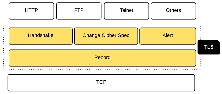
Figure 7. TLS protocol layers
Transport Layer Security (TLS) Handshake
Similar to the 3-way TCP handshake, TLS too introduces its own handshake. The TLS handshake includes three subprotocols: the Handshake protocol, the Change Cipher Spec protocol, and the Alert protocol (see Figure 7). The Handshake protocol is responsible for building an agreement between the client and the server on cryptographic keys to be used to protect the application data. Both the client and the server precede the Change Cipher Spec protocol to indicate to the other party that it’s going to switch to a cryptographically secured channel for further communication. The Alert protocol is responsible for generating alerts and communicating them to the parties involved in the TLS connection. For example, if the server certificate the client receives during the TLS handshake is a revoked one; the client can generate the certificate_revoked alert.
The TLS handshake happens after the TCP handshake. For the TCP or for the transport layer, everything in the TLS handshake is just application data. Once the TCP handshake is completed the TLS layer will initiate the TLS handshake. The Client Hello is the first message in the TLS handshake from the client to the server. As you can see in the Figure 8, the sequence number of the TCP packet is 1, as expected, since this is the very first TCP packet, which carries application data. The Client Hello message includes the highest version of the TLS protocol the client supports, a random number generated by the client, cipher suites and the compression algorithm supported by the client, and an optional session identifier (see Figure 9). The session identifier is used to resume an existing session rather than doing the handshake again from scratch. The TLS handshake is very CPU intensive, but with the support for session resumption, this overhead can be minimized.
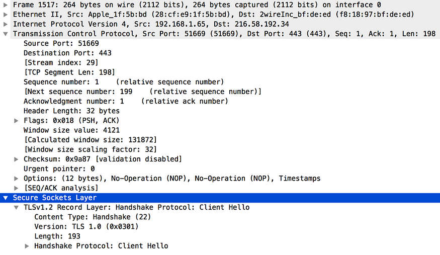
Figure 8. TLS Client Hello captured by Wireshark
TLS session resumption has a direct impact on performance. The master key–generation process in the TLS handshake is extremely costly. With session resumption, the same master secret from the previous session is reused. It has been proven through several academic studies that the performance enhancement resulting from TLS session resumption can be up to 20%. Session resumption also has a cost, which is mostly handled by servers. Each server has to maintain the TLS state of all its clients and also to address high-availability aspects; it needs to replicate this state across different nodes in the cluster.
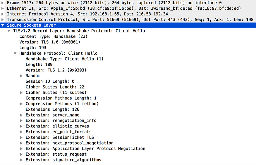
Figure 9. TLS Client Hello expanded version captured by Wireshark
One key field in the Client Hello message is the Cipher Suites. Figure 11 expands the Cipher Suites field of Figure 9. The Cipher Suites field in the Client Hello message carries all the cryptographic algorithms supported by the client. In the sample captured in Figure 11 shows the cryptographic capabilities of the Firefox browser version 43.0.2 (64-bit). A given cipher suite defines the sever authentication algorithm, key exchange algorithm, the bulk encryption algorithm and the message integrity algorithm. For example, in TLS_ECDHE_RSA_WITH_AES_128_GCM_SHA256 cipher suite, RSA is the authentication algorithm, ECDHE is the key exchange algorithm; AES_128_GCM is the bulk encryption algorithm and SHA256 is the message integrity algorithm. Any cipher suite starts with TLS, is only supported by the TLS protocols. As we proceed in this chapter we will learn the purpose of each algorithm.
Once the server receives the Client Hello message from the client, it responds back with the Server Hello message. The Server Hello is the first message from the server to the client. To be precise, the Server Hello is the first message from the server to the client, which is generated at the TLS layer. Prior to that TCP layer of the server responds back to the client with a TCP ACK message (see Figure 10). All TLS layer messages are treated as application data by the TCP layer and each message will be acknowledged either by the client or the server. From here onward we will not talk about TCP ACK messages.
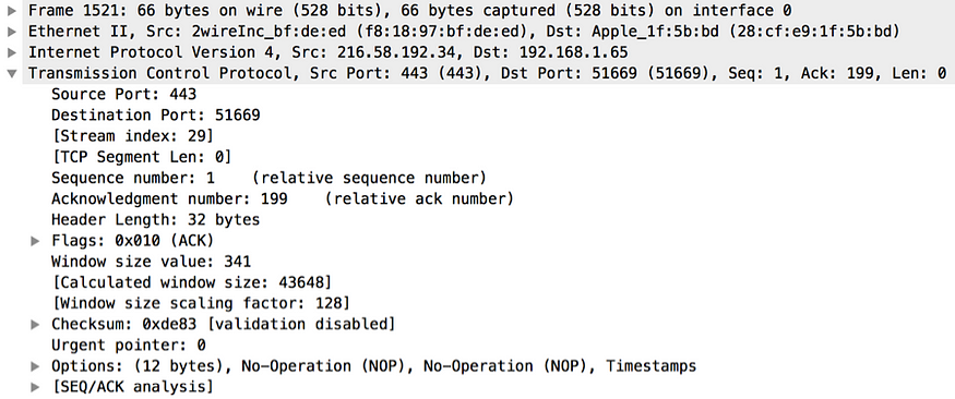
Figure 10. TCP ACK message from the server to the client
The Server Hello message includes the highest version of TLS protocol that both the client and the server can support, a random number generated by the server, the strongest cipher suite, and the compression algorithm that both the client and the server can support (see Figure 12). Both parties use the random numbers generated by each other (the client and the server) independently to generate the master secret. This master secret will be used later to derive encryption keys. To generate a session identifier, the server has several options. If no session identifier is included in the Client Hello message, the server generates a new one. Even the client includes one; but if the server can’t resume that session, then once again a new identifier is generated. If the server is capable of resuming the TLS session corresponding to the session identifier specified in the Client Hello message, then the server includes it in the Server Hello message. The server may also decide not to include any session identifiers for any new sessions that it’s not willing to resume in the future.
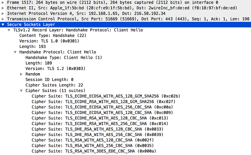
Figure 11. Cipher suites supported by the TLS Client captured by Wireshark
In the history of TLS, several attacks have been reported against the TLS handshake. Cipher suite rollback and version rollback are a couple of them. This could be a result of a man-in-the-middle attack, where the attacker intercepts the TLS handshake and downgrades either the cipher suite or the TLS version, or both. The problem was fixed from SSL 3.0 onward with the introduction of the Change Cipher Spec message. This requires both parties to share the hash of all TLS handshake messages up to the Change Cipher Spec message, exactly as each party read them. Each has to confirm that they read the messages from each other in the same way.
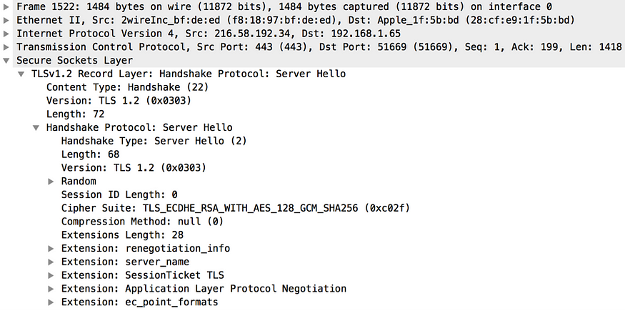
Figure 12. TLS Server Hello captured by Wireshark
After the Server Hello message is sent to the client, the server sends its public certificate, along with other certificates, up to the root certificate authority (CA) in the certificate chain (see Figure 13). The client must validate these certificates to accept the identity of the server. It uses this public key from the server certificate to encrypt the premaster secret key later. The premaster key is a shared secret between the client and the server to generate the master secret. If the public key in the server certificate isn’t cable of encrypting the premaster secret key, then the TLS protocol mandates another extra step, known as the Server Key Exchange (see Figure 13). During this step, the server has to create a new key and send it to the client. Later the client will use it to encrypt its premaster secret key.
If the server demands TLS mutual authentication, then the next step is for the server to request the client certificate. The client certificate request message from the server includes a list of certificate authorities trusted by the server and the type of the certificate. After the last two optional steps, the server sends the Server Hello Done message to the client (see Figure 13). This is an empty message that only indicates to the client that the server has completed its initial phase in the handshake.
If the server demands the client certificate, now the client sends its public certificate along with all other certificates in the chain up to the root certificate authority (CA) required to validate the client certificate. Next is the Client Key Exchange message, which includes the TLS protocol version as well as the premaster secret key (see Figure 14). The TLS protocol version must be the same as specified in the initial Client Hello message. This is a guard against any rollback attacks to force the server to use an unsecured TLS/SSL version. The premaster secret key included in the message should be encrypted with the server’s public key obtained from the server certificate or with the key passed in the Server Key Exchange message.
The Certificate Verify message is the next in line. This is optional and is needed only if the server demands client authentication. The client has to sign the entire set of TLS handshake messages that have taken place so far with its private key and send the signature to the server. The server validates the signature using the client’s public key, which was shared in a previous step. The signature-generation process varies depending on which signing algorithm picked during the handshake. If RSA is being used, then the hash of all the previous handshake messages is calculated with both MD5 and SHA-1. Then the concatenated hash is encrypted using the client’s private key. If the signing algorithm picked during the handshake is DSS (Digital Signature Standard), only a SHA-1 hash is used, and it’s encrypted using the client’s private key.
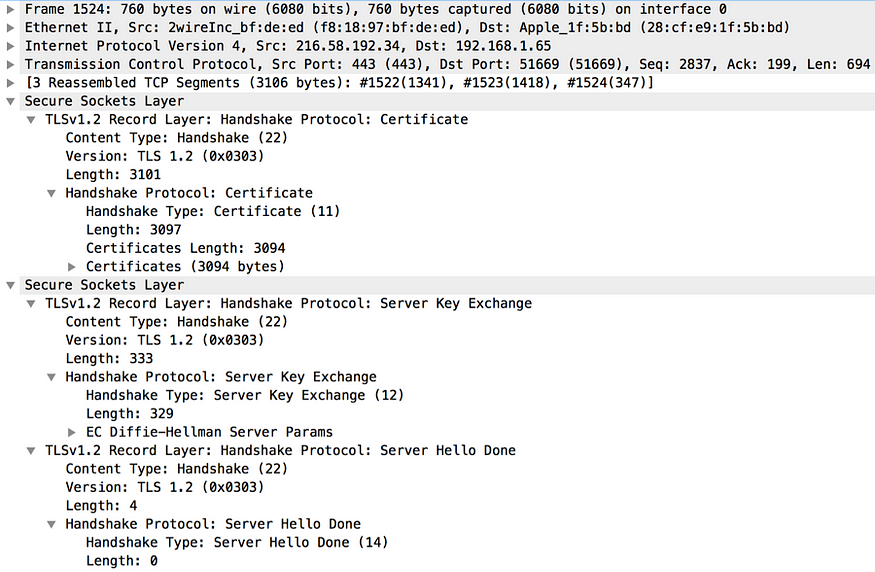
Figure 13. Certificate, Server Key Exchange and Server Hello Done captured by Wireshark
At this point, the client and the server have exchanged all the required materials to generate the master secret. The master secret is generated using the client random number, the server random number, and the premaster secret. The client now sends the Change Cipher Spec message to the server to indicates that all messages generated from here onward are protected with the keys already established (see Figure 14).
The Finished message is the last one from the client to the server. It’s the hash of the complete message flow in the TLS handshake encrypted by the already-established keys. Once the server receives the Finished message from the client, it responds back with the Change Cipher Spec message (see Figure 15). This indicates to the client that the server is ready to start communicating with the secret keys already established. Finally, the server will send the Finished message to the client. This is similar to the Finished message generated by the client and includes the hash of the complete message flow in the handshake encrypted by the generated cryptographic keys. This completes the TLS handshake and here onward both the client and the server can send data over an encrypted channel.
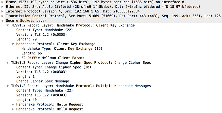
Figure 14. Client Key Exchange and Change Cipher Spec captured by Wireshark
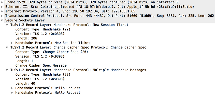
Figure 15. Server Change Cipher Spec captured by Wireshark
HTTP operates at the application layer of the TCP/IP stack, while the TLS operates between the application layer and the transport layer (see Figure 1). The agent (e.g. the browser) acting as the HTTP client should also act as the TLS client to initiate the TLS handshake, by opening a connection to a specific port (default 443) at the server. Only after the TLS handshake is completed, the agent should initiate the application data exchange. All HTTP data are sent as TLS application data. HTTP over TLS was initially defined by the RFC 2818, under the IETF network working group. The RFC 2818 further defines an URI format for HTTP over TLS traffic, to differentiate it from plain HTTP traffic. HTTP over TLS is differentiated from HTTP URIs by using the https protocol identifier in place of the http protocol identifier. The RFC 2818 was later updated by two RFCs: RFC 5785 and RFC 7230.
Application Data Transfer
After the TLS handshake phase is complete, sensitive application data can be exchanged between the client and the server using the TLS Record protocol. This protocol is responsible for breaking all outgoing messages into blocks and assembling all incoming messages. Each outgoing block is compressed, MAC is calculated, and encrypted. Each incoming block is decrypted, decompressed, and MAC verified. The Figure 17 summarizes all the key messages exchanged in the TLS handshake.
During the TLS handshake, each side derives a master secret using the client-generated random key, the server-generated random key, and the client-generated premaster secret. All these three keys are shared between each other during the TLS handshake. The master secret is never transferred over the wire. Using the master secret, each side generates four more keys. The client uses the first key to calculate the MAC (message authentication code) for each outgoing message. The server uses the same key to validate the MAC of all incoming messages from the client. The server uses the second key to calculate the MAC for each out going message. The client uses the same key to validate the MAC of all incoming messages from the server. The client uses the third key to encrypt outgoing messages, and the server uses the same key to decrypt all incoming messages. The server uses the fourth key to encrypt outgoing messages, and the client uses the same key to decrypt all incoming messages.

Figure 16. Server Change Cipher Spec captured by Wireshark
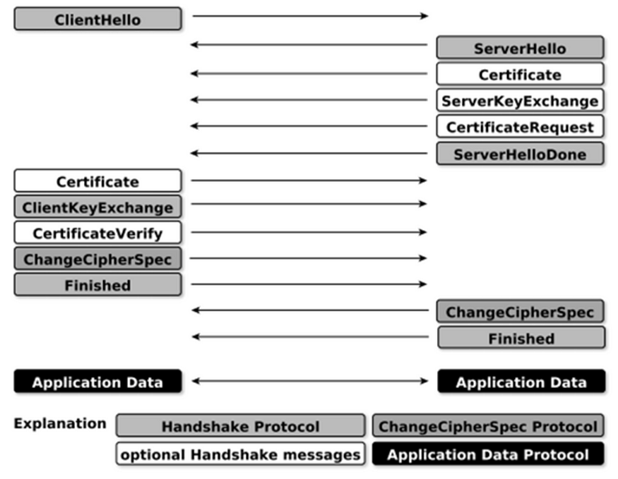
Figure 17. TLS handshake
Summary
Transport Layer Security (TLS) provides a guarantee on the integrity and the confidentiality of the data transported over a communication channel. Further it provides mutual authentication to identify strongly the two parties at the each end of the communication channel. This blog focused on building a foundation related to TLS and its evolution.


1